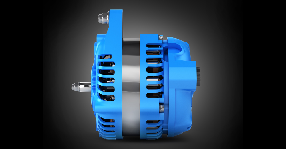
Automotive batteries cannot meet the needs of the electrical system for extended periods of time. It’s the job of the alternator to restore electrical power to the battery. The alternator is also needed to supply current to the electrical accessories when the engine is running.
Alternators have been used in production vehicles since the 1960s, when they first made an appearance in the Plymouth Valiant. Up until then, direct current (DC) generators were used. Both DC generators and AC current alternators rely on a phenomenon known as electromagnetic induction.
Electromagnetic Induction
Electromagnetic induction occurs when electricity is created by moving a conductor through a magnetic field. It can also occur when a magnet field passes through a conductor. To create electricity in a DC generator, the conductor is rotated and the field is held. In an alternator, the conductor is held stationary and the field is rotated.
While they are much the same, the generator was not able to produce adequate current to power the number of electrical accessories on modern vehicles. Because of this, it was dropped in favor of the alternator.
The Rotor, Stator and Diodes
The advent of semi-conductors is responsible for the creation of many devices, from the home computer to the transistor radio. The alternator is one such device that relies on a semi-conductor called a diode. The diode allows current to pass in only one direction and not the other. This converts alternating current (AC) voltage into direct current (DC) voltage the vehicle can use.
The alternator is designed to convert mechanical energy into electrical energy. It is driven off the engine crankshaft by a belt. The belt turns a pulley, which is attached to the rotor shaft. The rotor is a magnetic iron core wrapped in a coil of wire. The two ends of the coil attach to copper slip rings that then attach to brushes. One of the brushes is attached to ground and the other is attached to the field terminal in the voltage regulator. The spinning belt turns the rotor, which is positioned inside the stator. Since the rotor is a magnet and the stator is a conductor, turning the rotor creates electricity in the stator windings. This is induction at work.
There are three coils of wire inside the stator, each generating its own AC voltage. This voltage must be converted to DC before it can be used to charge the battery and power the electrical accessories. This is the job of the diodes inside the rectifier bridge. As was mentioned, diodes are solid-state semiconductors used to allow current to pass in only one direction. The diode blocks the negative voltage output from each stator coil, so only positive voltage reaches the vehicle. To visualize this, think of AC voltage, which is a sinewave. After the voltage goes through the rectified bridge, the sinewave is cut in half along its horizontal axis.
Voltage Regulators
Alternators require a voltage regulator to control the output of electricity. To accomplish this task, the regulator switches the rotor control circuit on and off, reducing its magnetic field. As a result, the voltage entering the stator is reduced, as is overall alternator output. Old alternators used an externally mounted regulator, or a regulator that is internal to the alternator. These could be either mechanical or electronically controlled.
On modern vehicles, voltage regulation is the responsibility of the powertrain control module (PCM). There is no need for a separate regulator. In most cases, the PCM monitors battery voltage, engine speed and battery temperature. It then pulses the alternator’s field coil to control output.
Charge Indicators
Gauges and warning lights are used to alert the driver of a problem with the charging system. Older vehicles use ammeters for this purpose, while modern vehicles use voltmeters or warning lights. Voltmeters are connected in parallel to the charging system and are used to measure charging system voltage. A voltmeter has a coil of wire located between two magnets. As current from the charging system increases, the coil of wire moves causing a pointer to move across the gauge.
Voltmeters are known for their inaccuracy, which is why most manufacturers have switched to warning lights. In most cases, charge warning indicators receive power from the ignition switch. They are grounded through the voltage regulator. When the ignition is turned on and the engine is not running, the indicator has a complete circuit and will illuminate. When the engine is started, voltage increases. This causes the indicator to lose ground and eventually go out. If there is a problem with the charging system, the indicator will continue to receive ground from the regulator. This will keep it illuminated.
The alternator is extremely important. Without it, your vehicle won’t stay running for long (or worse yet, your radio won’t function). Hopefully, you now have a basic understanding of how the alternator works.

