While Toyota and Lexus have always been known as relatively reliable vehicles, they still suffer from ignition coil failures like any other manufacturer. When testing a coil-on-plug (COP) ignition system, one of the first steps is to understand the system operation. The location of the ignition module that actually drives ignition primary coil is located in each COP. Toyota calls this module the igniter. The PCM still decides when to fire the ignition coil based on various inputs. The PCM sends a trigger signal to the COP to fire the coil, and the module in the COP has a module to control the primary circuit. This is how most manufacturers control their COP ignition systems today, however Toyota adds a unique feature.
Toyota also has a feedback circuit to test the ignition system. Many manufacturers have ways to test the ignition primary circuit built into the PCM, and as a technician we do not see the actual circuitry or wiring. Toyota’s feedback circuit is fairly simple, they send a reference voltage out to a splice that goes to each coil. When a coil fires, it pulls the signal towards ground. This is how the PCM can verify that the coil fired when it sends the trigger signal; it is a closed loop system.
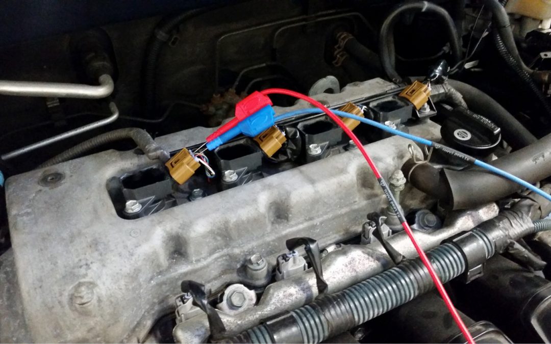
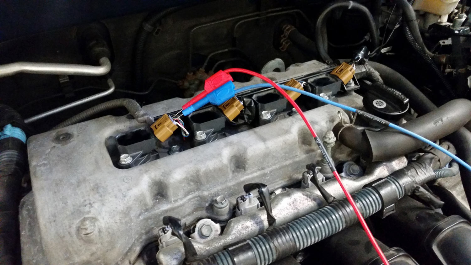
Toyota’s ignition system with feedback can be identified by seeing a four-wire COP unit. Be careful when servicing this system, the locking tab on the connectors are very prone to breaking. I have found that using a pocket screwdriver to pull up on the lock tab works much better than pressing the button on the connector. If you do break the locking tab, they are easy to fix. The connector body is available from the dealer for a fair price, simply pin out the four wires and put them into the new shell.
(Fig. 1)
Here are the 4 wires going to a Toyota COP (Fig. 1):
- IGF – Ignition Feedback, this is the feedback circuit discussed above
- IGT – Ignition Timing, this is the signal from the PCM to fire the coil
- B+ – Ignition switch voltage to power the ignition primary circuit
- GND – Ground for the COP
Testing COP systems can be challenging. There is a reason our big box ignition analyzers are sitting in the corner of the shop collecting dust. COP systems make secondary ignition voltage difficult to obtain, but there are other great ways to test these systems. For this system, we will use a scope to check the trigger from the PCM, the feedback circuit and primary ignition current. Many manufacturers do not use DSO diagnostics in their dealerships, however Toyota recommends using a scope on these systems. Service information will actually include known good waveforms and thorough information about the system.
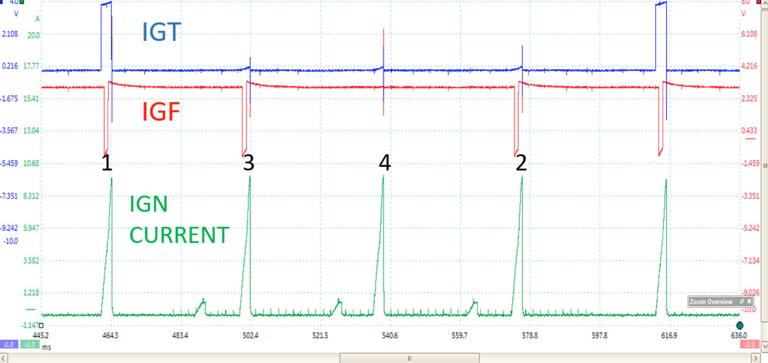
Here is a known good waveform of 1ZZ-FE. There is no need to worry about high voltage and your scope; there is no access to the primary voltage since the module and primary coil are sealed together in the COP. The blue channel is the trigger signal for the #1 COP. The red channel is the feedback circuit, notice that we see the signal for all 4 cylinders since the wire is spliced together. Green is the ignition coil current. I am tapped into the fuse that also feeds the fuel injectors. Being on the same fuse and the injectors will not have any effect on our testing here. (Fig. 2)

(Fig. 2)
A 2008 Toyota Corolla came to me with a check engine light and misfire.
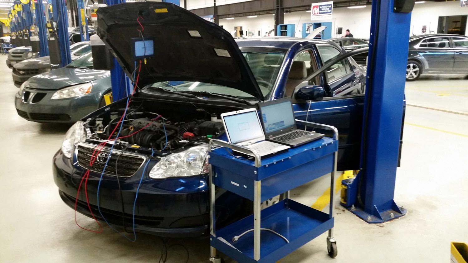
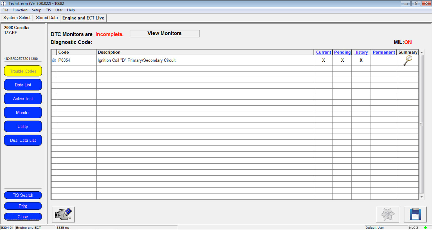
I scanned the vehicle for codes and found a P0354: Ignition coil “D” primary/secondary circuit. Ignition coil D is cylinder 4.
Ignition coils are a common failure for this vehicle, so I swapped the coils with no change. Time to do some more involved testing. Upon further research, I find that this code is set when the IGF signal is missing for the #4 ignition coil at the PCM and a bad ignition coil can be the cause. Coils fail in two ways. Coils can fail where they do not fire the spark plug, which will obviously cause an issue. There are some cases however where the ignition coil is firing fine, but the coil is not capable of pulling the IGF signal to ground. This code can also be caused by an open in the IGF circuit, and very rarely a PCM issue. Here is a waveform taken from the problem vehicle. (Fig. 5)
(Fig. 5)
The ignition coil current in green looks good for all four cylinders. The actual ignition coil is firing just fine, but I notice the IGF signal is missing for cylinder 4. In retrospect, I should have started my testing on cylinder 4, so I added a channel to the IGF on cylinder 4. (Fig. 6)

(Fig. 6)
At cylinder 4 the IGF signal is missing. Upon further investigation, I found a broken IGF wire about 6 inches away from the coil, before the splice. The question is, why was the vehicle misfiring if the coil was still firing OK? There was just and IGF issue, no issues are present with the actual ignition coil. When a Toyota has an ignition coil code, the PCM shuts off the fuel injector to that cylinder. This is a catalyst protection strategy. Many manufacturers do this since they have to warranty such an expensive part for 8 years or 80,000 miles. If you go back and look at figure 5, you will also notice that one of the fuel injector current waveforms was missing.
After fixing the wire and clearing the codes the vehicle was fixed. Toyota COP systems may be different than the others, but with a little knowledge about the system they are easily diagnosed. When diagnosing a COP system fault we must determine if the issue is coil related, or feedback circuit related. In our case study we had a failure on the system that was supposed to detect the failure.
 Article By:
Matthew Shanahan
Listen to his Technician.Academy podcast here.